
Civil 3D Breakline Types: Because One Kind Was Not Enough

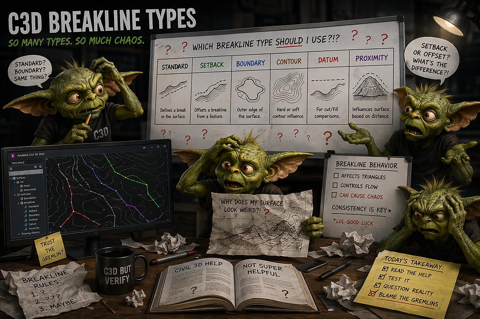
Most Civil 3D users learn about breaklines in the usual way.
A surface looks terrible. Someone says, “Add a breakline.”You add a breakline. The surface changes. Everyone pretends this was the plan.
But then one day you open the Add Breaklines dialog box and notice something that has been there for years, but you are just discovering it now:
There is more than one type of breakline.
Because of course there is.
Breaklines are not just “lines that make the surface behave.” They are instructions to the surface, and Civil 3D gives you a few different flavors of those instructions. Some are used constantly. Some are used occasionally. Some sit quietly in the dialog box waiting for the one specific day they are useful.
Let’s keep this simple.
Where Do You Pick the Breakline Type?
You assign the breakline type when you add the breakline to a surface.
Go to:
Toolspace → Prospector → Surfaces → [Your Surface] → Definition → Breaklines → right-click Add
That opens the Add Breaklines dialog box.
In that dialog, there is a Type dropdown.
That is where you choose what kind of breakline you are adding.
Important note: the breakline type is not really about what the object “is” in the drawing. It is about how Civil 3D uses that object when adding it to the surface definition.
A feature line does not walk around wearing a little sash that says “Standard Breakline.” You decide how it gets used when you add it to the surface.
Civil 3D is many things, but it is not psychic. Unfortunately.
Standard Breaklines
Standard breaklines are the everyday breaklines.
This is probably what most people mean when they say, “Add that as a breakline.”
A standard breakline uses the elevations from the object you select. That object might be a feature line, 3D polyline, 3D line, spline, or other supported elevated geometry depending on your workflow and Civil 3D version.
Use a standard breakline when the selected geometry already has the elevations you want the surface to honor.
Good examples include:
Edge of pavement
Top or toe of slope
Swales
Berms
Ditches
Pads
Curbs
Ridges
Design feature lines
The key phrase is:
The object already knows its elevations.
If the line has good elevations, a standard breakline can be your friend.
If the line has bad elevations, a standard breakline becomes a tiny terrain crime scene.
This is why plan view cannot be trusted. A line can look perfect from above while secretly containing one vertex at an elevation last seen by weather balloons.
Use standard breaklines often.
Just make sure the geometry deserves that level of authority.
Proximity Breaklines
Proximity breaklines are a little different.
Instead of relying on the selected object’s own elevations, Civil 3D uses nearby surface points to determine the elevations at the breakline vertices.
In plain language:
The linework gives Civil 3D the horizontal path.The existing surface data helps provide the elevations.
This can be useful when you have 2D linework that traces something important, but the line itself does not have useful elevation data.
For example, maybe you have linework drawn from point to point over an existing ground surface. The line is useful horizontally, but you want the surface points nearby to inform the vertical data.
Best use case:
You trust the nearby surface data more than the line’s own elevations.
That is the entire emotional journey.
Do not use proximity breaklines when you need the line itself to control the proposed design elevation. That is usually standard breakline territory.
Proximity breaklines are useful, but they are not magic. Their accuracy depends on the relationship between the selected linework and the nearby surface points.
So if the linework is vague, sloppy, or wandering around like it is looking for snacks, do not expect perfection.
Wall Breaklines
Wall breaklines are for situations where there is a vertical or near-vertical difference between two sides of a feature.
Think:
Retaining walls
Curbs
Steps
Sharp grade separations
Features where one side is higher or lower than the other
A normal TIN surface does not truly model vertical faces the way a solid model might. It triangulates. So when you need to represent a sharp elevation difference, wall breaklines give Civil 3D more information about how to treat the two sides.
When creating a wall breakline, you define things like the offset side and elevation difference. That helps Civil 3D represent the level change more accurately than just throwing one line at the surface and hoping for emotional growth.
Use wall breaklines when one linear feature needs to represent different elevations on either side.
Do not use them just because the word “wall” feels fancy.
If the object is simply a grade break with elevations already assigned, a standard breakline may be enough. If there is a distinct top/bottom or side-to-side elevation difference that needs to be represented, then wall breaklines enter the chat.
Non-Destructive Breaklines
Non-destructive breaklines are the “please influence the triangles without wrecking the original surface” option.
They are used when you want to control triangulation while maintaining the integrity of the original surface data.
That sounds very polite because it is.
A non-destructive breakline can be useful when you need to guide how the surface triangulates, but you do not want to introduce new elevations or alter the surface in the same way a standard breakline would.
Use this when the goal is triangle control, not new vertical design information.
That is the big difference.
Standard breakline: Honor these elevations.
Non-destructive breakline: Adjust the triangle behavior, but do not treat this like new elevation data.
This is one of those tools that may not be part of your daily workflow, but it is good to know it exists before you spend twenty minutes yelling at triangles.
Not that any of us would do that.
Professionals would never.
From File Breaklines
The From File option is used to import breakline data from an external file format.
This is not usually the first stop for everyday surface editing. It is more of a data-import workflow when breakline information is coming from outside the current drawing.
Use this when your breaklines are being provided in a supported external file and you need to bring them into the surface definition.
If you are manually selecting feature lines or 3D polylines in the drawing, you are probably not using this option.
It is there for a reason.
That reason is just not always your Tuesday afternoon grading panic.
So Which Type Should You Use?
Here is the simple version.
Use Standard when the selected geometry already has the correct elevations.
Use Proximity when the linework gives the path, but nearby surface points should provide the elevations.
Use Wall when you need to represent a curb, wall, or sharp side-to-side elevation difference.
Use Non-Destructive when you want to influence triangulation without adding new elevation data.
Use From File when the breakline data is coming from an external file.
Most of the time, you will probably use Standard.
That does not mean the other types are useless. It just means Standard is the workhorse. The others are more situational.
Civil 3D loves situational tools.
It collects them like project folders collect PDFs named “Final.”
Final Thought
Breakline types matter because they tell Civil 3D how to use the geometry.
The same linework can behave differently depending on the type of breakline you choose when adding it to the surface.
So before clicking OK like you are trying to escape the dialog box before it asks follow-up questions, pause for a second.
Ask:
Does this object already have good elevations? Am I using nearby surface points for elevation? Is this a wall or curb condition? Am I only trying to control triangulation? Is this data coming from a file?
Pick the type that matches the job.
Because breaklines are not just lines.
They are instructions.
And Civil 3D will follow bad instructions with the confidence of someone who did not have to attend the project meeting.
Thanks for stopping by the Den! It's not a bug, it’s a feature. Allegedly.
Images provided by Copilot 2026.

Comments