
Contours Aren't Magic: We Used to Draw This Crap by Hand!!

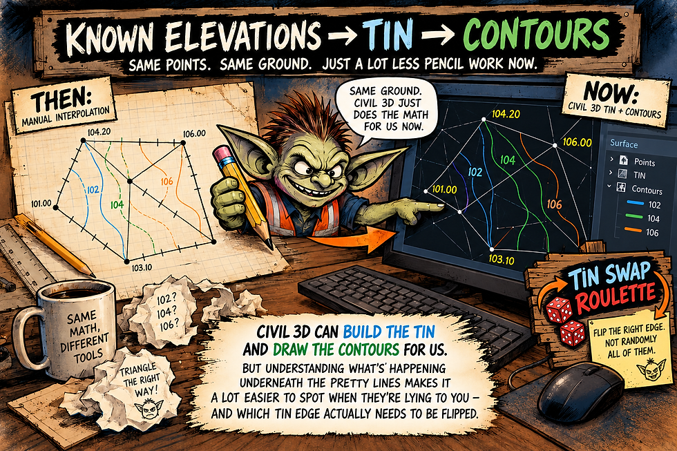
Civil 3D makes creating a surface look suspiciously easy.
Give it some data. Build a surface. Contours appear. It's magical!
Excellent. Moving on.
Except understanding what is happening underneath those contours can explain a whole lot about why surfaces occasionally seem possessed.
So we're going old school.
Before software handled all of this for us, contours were developed manually from surveyed elevations by interpolating between known points.
We're going to do a tiny version of that.
Not because I expect anyone to throw Civil 3D away and grab a pencil.
Because once you understand where contours come from, Civil 3D surfaces — and editing their TINs — make a whole lot more sense.
It's also one of those fundamentals that seems to get skipped over a lot these days.
Start With What We Actually Know
Imagine we've surveyed a small patch of ground.
We have points with horizontal locations and elevations.
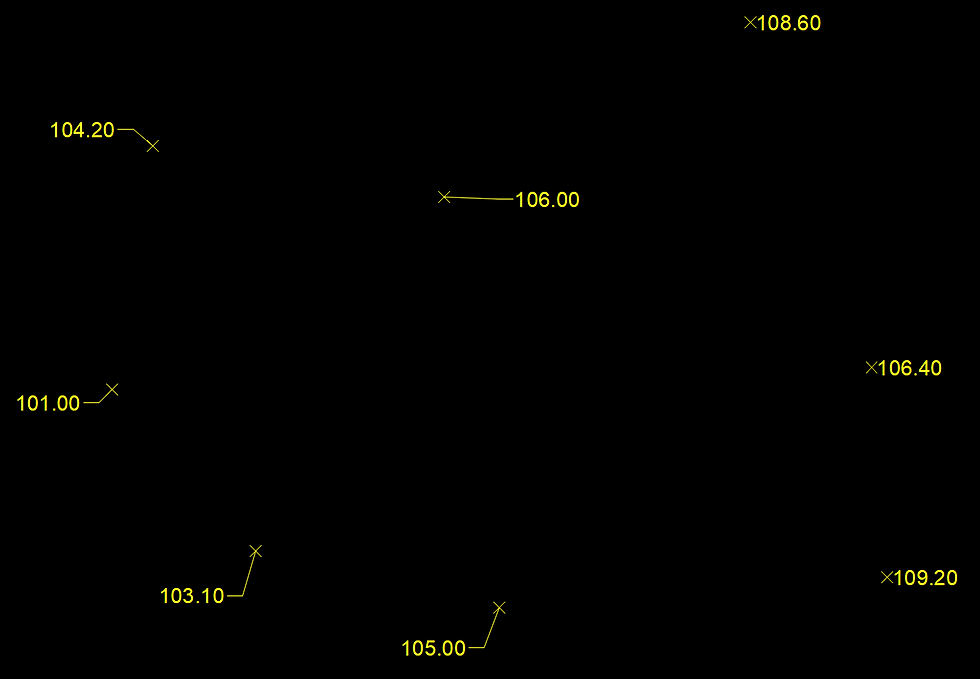
Those surveyed elevations are our known information - horizontal location and elevation.
But here's the problem:
What is the ground elevation between those points?
We didn't measure every square inch of dirt.
Somehow, we need to model what happens between the locations we did measure.
This Is Where Triangles Become Useful
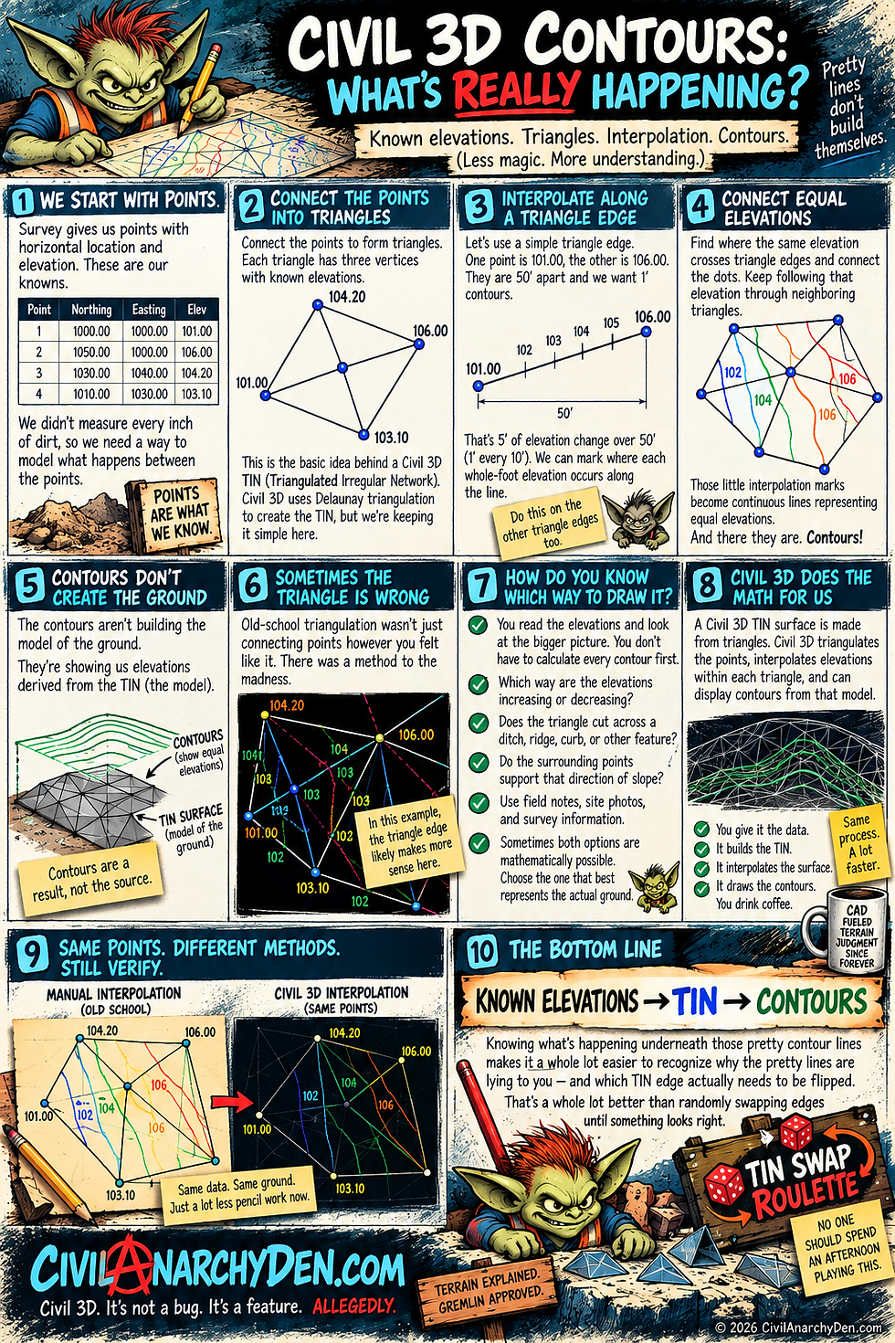
If we connect our known points into triangles, each triangle has three vertices with known elevations.
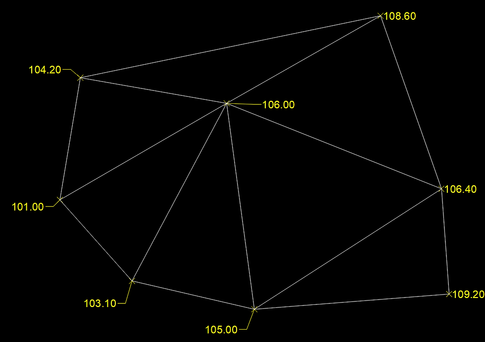
Now we have something we can work with.
Within each triangle, we can interpolate between those known elevations to represent the ground between the measured points.
That basic idea is also at the heart of a Civil 3D TIN — Triangulated Irregular Network.
There is a lot more math involved in Civil 3D's actual triangulation than we're doing with our imaginary pencil. When Civil 3D creates a TIN from point data, it uses Delaunay triangulation...yeah, I had to look that up...I'm not a math kid, so I am glad that C3D does the math for us.
We're not recreating that algorithm here.
We're just trying to understand what those triangles are doing for us.
Now Comes the Part I'm Glad the Computer Does
Let's zoom in on one simple triangle edge. We are going to use a very easy edge and elevation change for this example.
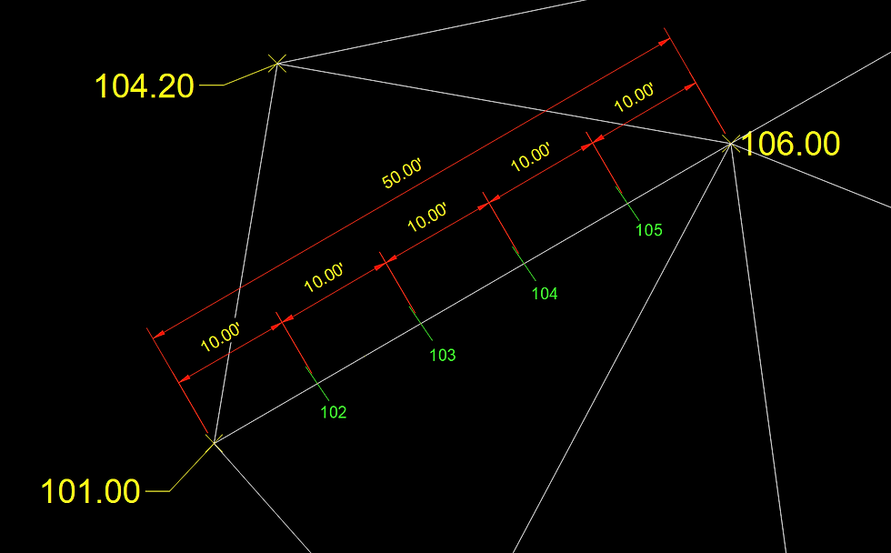
One end has an elevation of: 101.00
The other end is: 106.00
Those two points are 50 feet apart.
And let's say we want contours every 1 foot.
Somewhere along that line we need to locate elevations:
102, 103, 104, and 105
We've got 5 feet of elevation change over 50 horizontal feet.
So the elevation changes 1 foot for every 10 feet of horizontal distance along this line.
We can mark where each whole foot elevation occurs along that line.
Now repeat that interpolation on the other triangle edges.

Then move on to the other triangles.

This is also the point where I would like to formally thank computers and software!!
Connect Equal Elevations
Now things are starting to look familiar.
We've determined where elevation 104 crosses one triangle edge.
We've determined where that same elevation crosses another edge.
Connect those locations.
Continue following that elevation through the neighboring triangles.
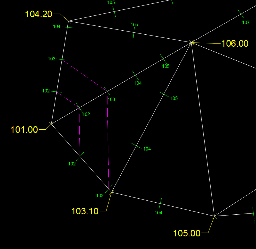
Do the same thing for the other contour elevations.
Eventually all those little interpolation marks become continuous lines representing locations of equal elevation.
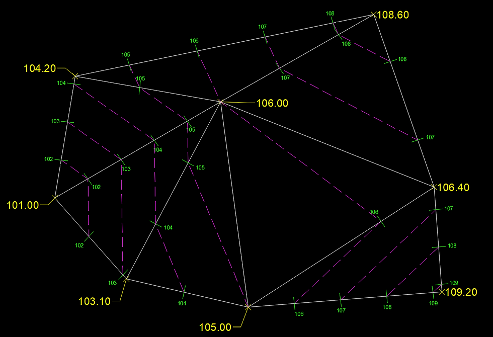
And there they are. Contours! This is beyond tedious to do across an entire site.
The important concept is:
The contours aren't creating this model of the ground.
They're showing us elevations derived from it.
That's a useful distinction when we move into Civil 3D.
Now the Deep Dive part of this
You calculated all of this manually, marked everything out and started drawing contours when...
Oh crap. That triangle is probably wrong.
Old-school triangulation wasn't just connecting points however you felt like it. There was a method to the madness.
If you've looked at enough surface TINs, you probably already see a few questionable triangles in our example. Below, the triangle edge likely makes more sense running along the blue line.
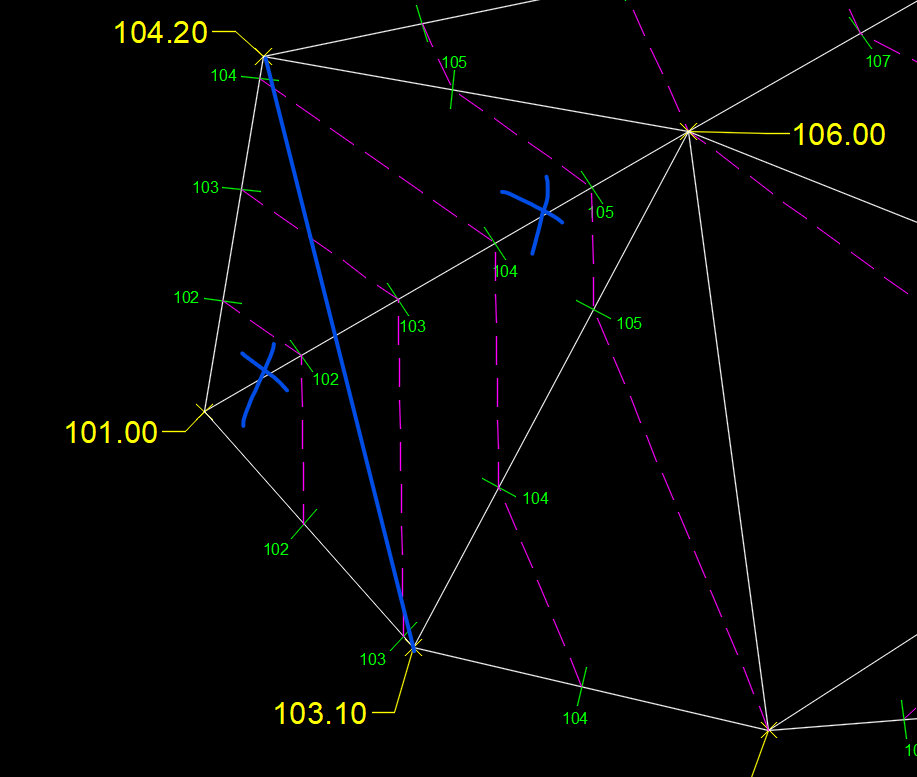
So how did they figure that out without calculating every possible contour first?
They learned to read the elevations.
Look at which direction the elevations are increasing or decreasing and how the surrounding points relate to each other. From that, you can start seeing the general shape and slope of the ground before calculating every contour crossing.
Known terrain features, field notes, site photos, and survey information helped even more. A ditch, ridge, curb or other break in the terrain gave you clues about how those points should connect.
There is one catch: sometimes the elevations alone aren't enough to know which triangle is correct. Both options can be mathematically possible. The goal is choosing the one that best represents the actual ground.
This is where the old-school method was part math and part art.
The math told you what was possible. Experience told you what made sense. And the site photos, field notes, and survey info helped confirm your decision.
And really, we still do the same thing in Civil 3D.
The software just draws the triangles first.
Then occasionally we look at one and say:
“Yeah... no. Swap Edge.”
Now Hand the Tedious Part to Civil 3D
A Civil 3D TIN surface is made from triangles.
When Civil 3D creates a TIN from point data, it triangulates those points. Each triangle has three vertices with known elevations, and elevations within that triangle can be interpolated from the elevations of those vertices.
From that surface model, Civil 3D can display contours representing equal elevations.
So conceptually, we're looking at:
KNOWN ELEVATIONS → TIN → INTERPOLATED SURFACE ELEVATIONS → DISPLAYED CONTOURS
Civil 3D handles the calculations.
We get to drink coffee and complain about something else.
Same Points. Different methods. Still Verify.
Manual interpolation
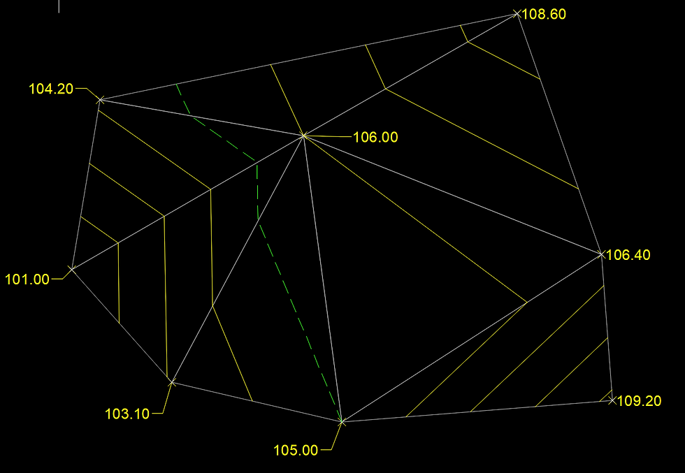
Civil 3D interpolation
THE MATH CHANGED HANDS. THE RESPONSIBILITY DIDN'T.
Civil 3D can build the TIN. We still have to decide if it truly represents the ground.
KNOWN ELEVATIONS → TIN → CONTOURS
That's really the point of this entire exercise.
Thankfully, we don't have to manually interpolate contours anymore.
We don't need to sit there with a scale figuring out where 104.00 falls between two survey shots. Civil 3D will happily do an enormous amount of that work for us.
But knowing what's happening underneath those pretty contour lines makes it a whole lot easier to recognize why the pretty lines are lying to you — and which TIN edge actually needs to be flipped.
That's a whole lot better than randomly swapping edges until something looks right.
Because no one should spend an afternoon playing:
TIN Swapping Roulette
Thanks for stopping by the Den.
Civil 3D. It's not a bug, it's a feature. Allegedly.
And again, to test how AI crunched my article for a quick handout/reference...
Images provided by ChatGPT 2026.



Comments