
Pipe Networks: Basics on Pipes, Structures, and Lies We Tell Ourselves


Basic Civil 3D Pipe Anatomy in plain English
Pipe Networks are one of those Civil 3D tools that seem pretty straightforward at first.
You have pipes.
You have structures.
You connect them together.
Congratulations! You have plumbing.
Except this is Civil 3D, so underneath those innocent-looking circles and lines is an entire ecosystem of networks, parts lists, catalogs, rules, elevations, surfaces, alignments, styles, connections, and settings quietly waiting for you to misunderstand one of them.
Before we start troubleshooting why your catch basin is the size of a small apartment building, it helps to understand what a Pipe Network actually is.
So let’s start with the basics.
First: What Exactly Is a Pipe Network?
A Pipe Network is basically a container.
Inside that container are individual Civil 3D objects:
Pipes
Structures
That distinction matters.
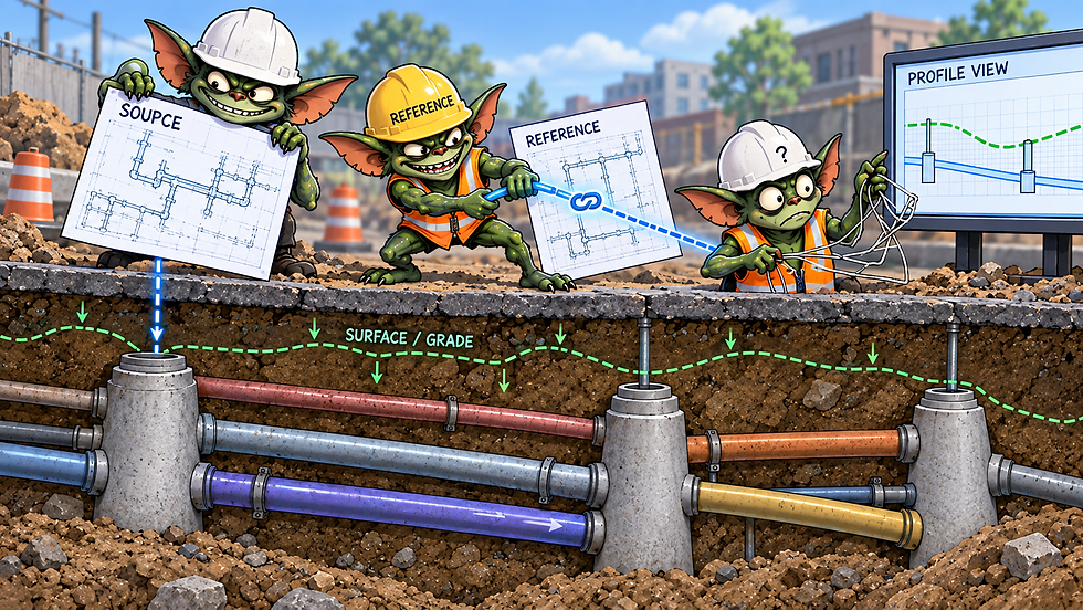
The network itself is not one giant piece of geometry. It is an object Civil 3D uses to organize a collection of pipes and structures that belong together. Those parts can then reference things like surfaces and alignments for elevation, station, and offset information.
Think of it like a folder.
The folder might be called:
Storm Sewer
Inside it are:
CB-1, Pipe-1, MH-1, Pipe-2, CB-2, and Pipe-3
Those are all individual objects living inside the Storm Sewer network.
Lie We Tell Ourselves #1:
“It’s all one network, so everything must be connected.”
Nope.
Civil 3D will happily allow pipes and structures to exist in the same Pipe Network without actually being connected to each other. Autodesk even notes that the components of a network do not have to be directly connected.
Same folder, but the objects aren't necessarily holding hands.
That becomes important later when labels, profiles, connected-pipe information, or editing behavior start acting strange.
The Pipe
The pipe is the easy one...Mostly.
A pipe is a Civil 3D object representing a length of pipe between two endpoints.
Depending on the part selected from the catalog, the pipe can have shapes such as:
Circular
Elliptical
Egg-shaped
Rectangular
It can also follow a straight or curved path.
But the important thing to understand is this:
A pipe is not just a line.
That line you see in plan view is only one representation of a 3D object.
The pipe knows things like:
Start elevation
End elevation
Length
Slope
Size
Inner and outer dimensions
Connected structures
Reference surface
Reference alignment
Style
Rules
That is why grabbing a pipe and treating it like a polyline can sometimes produce..."educational results".
Pipe Inverts
You will hear the word invert constantly when working with gravity Pipe Networks.
For the very beginners: invert is essentially the inside bottom of the pipe.
So if someone tells you:
“Set the downstream invert to 842.50.”
They are not talking about the centerline of the pipe or the outside bottom of the pipe.
They are talking about the flowline along the inside bottom.
That difference matters because a 36-inch pipe has significantly more pipe between its invert and crown than a 12-inch pipe.
Yes, I have seen this matter and yes, Civil 3D remembers which one you told it to be.
Whether we remember which one we meant is another matter entirely.
The Structure
Structures are the other major component of a gravity Pipe Network.
These are objects such as:
Manholes
Catch basins
Inlets
Junction structures
Headwalls
Unlike pipes, structures can be significantly more complicated geometrically because their shape is defined by the structure part selected from the catalog.
A structure may have properties for things such as:
Rim elevation
Sump elevation
Height
Width or diameter
Frame
Connected pipes
And here is one of the most important concepts for beginners:
The structure is not just the symbol you see in plan.
That circle representing a manhole?
Civil 3D does not think of it as just a circle.
There is an actual 3D structure object underneath it with dimensions, elevations, connection information, rules, and a 3D representation.
Lie We Tell Ourselves #2:
“It looks right in plan, so the structure must be right.”
Absolutely not.
You can make something look perfectly acceptable in plan while its rim, sump, dimensions, or pipe connections are quietly trying to dig to the center of the earth.
Always remember:
Plan view is only one witness, there are profile or vertical witnesses too.
Pipes + Structures = Connections
Normally a gravity Pipe Network looks something like this:
Structure → Pipe → Structure → Pipe → Structure
Most of the time the pipe endpoints are connected to structures.
Those connections are meaningful.
Civil 3D can determine which pipes are connected to a structure and maintain information about those relationships.
That means moving a structure can affect connected pipes.
Changing pipe sizes can affect how those pipes fit into a structure.
Changing elevations can affect drops through structures.
This is not AutoCAD geometry merely touching other AutoCAD geometry.
These objects actually know they are connected and interact.
Lie We Tell Ourselves #3:
“The pipe touches the structure, so they’re connected.”
Visually touching something is not the same thing as Civil 3D recognizing an object relationship.
Welcome to Civil 3D.
Where two objects can occupy the exact same location while maintaining the emotional distance of coworkers who had an argument three years ago.
The Part Catalog
Now we reach the first layer of Pipe Network bureaucracy.
The Part Catalog contains the definitions of pipe and structure parts available to Civil 3D.
Think of it as the warehouse of types of pipes.
Inside that warehouse might be definitions for:
Concrete pipe
PVC pipe
Ductile iron pipe
Circular structures
Rectangular structures
Catch basins
Headwalls
Various pipe sizes
Various structure sizes
The catalog defines the available types, shapes, families, and sizes of parts.
But you generally don't want Civil 3D handing every possible object in that warehouse to a designer every time they create a storm network.
Which brings us to...
The Parts List
The Parts List is a smaller selection of parts pulled from the larger catalog.
Think of it as your shopping list.
The catalog might contain 300 things.
Your project's Storm Parts List might contain only:
12" RCP
15" RCP
18" RCP
24" RCP
4' manhole
5' manhole
Standard catch basin
Civil 3D uses parts lists so you can limit users to the pipe and structure families and sizes appropriate for a particular project or workflow. Autodesk describes a parts list as a subset of the available catalog parts.
Lie We Tell Ourselves #4:
“If the part exists in Civil 3D, it should be available in my network.”
Not necessarily.
It can exist perfectly happily inside the catalog while not being included in the Parts List you are currently using.
So when someone says:
“Civil 3D doesn't have 30-inch pipe.”
The correct response may actually be:
“Civil 3D has it. Your Parts List doesn't.”
Those are two completely different problems.
Please troubleshoot accordingly before rebuilding the catalog and accidentally opening another reality dimension.
Then There Are the Rules
Pipe Networks can also have rules.
Pipe rules can evaluate things such as:
Minimum slope
Maximum slope
Minimum cover
Maximum cover
Pipe length
Structure rules can deal with things such as:
Pipe drop through a structure
Sump depth
Whether a pipe is too large for a structure
Rules can affect how parts are initially created and can also flag conditions that violate the criteria assigned to them.
And this brings us to an extremely important distinction.
Rules are not an engineer.
Lie We Tell Ourselves #5:
“Civil 3D used the rules, so the design must be correct.”
No.
No no no.
Rules are criteria Civil 3D can use when creating or checking parts.
A rule violation can create a warning.
A lack of rule violations does not mean Civil 3D has stamped the drawing:
ENGINEERING COMPLETE. EVERYONE GO HOME.
In fact, Autodesk specifically allows you to continue working even when pipe rules have been violated; Civil 3D flags the violation with warnings rather than preventing the design from existing.
Rules are helpers. Not designers. Not reviewers.
And definitely not replacements for QA/QC.
Surfaces and Alignments
A Pipe Network can also reference a:
Surface
Alignment
Or both
These references give Civil 3D additional context.
A surface can provide information used for things such as cover and elevations.
An alignment can provide station and offset information.
And individual parts within a network can reference those objects.
This is why Pipe Networks become much more useful once they stop being thought of as isolated objects floating around model space and start interacting with the rest of your Civil 3D model.
But it also means another dependency has entered the room.
Change the surface.
Change the alignment.
Move the pipe.
Swap the structure.
Apply the rules.
And suddenly the thing that looked perfectly innocent five minutes ago has opinions.
So What Should You Actually Remember?
If you are new to Pipe Networks, forget all the menus for a second.
Remember this hierarchy:
PIPE NETWORK : The container holding the system.
↓
PIPES + STRUCTURES : The actual Civil 3D objects.
↓
PARTS LIST : The approved menu of pipes and structures you can select.
↓
PART CATALOG : The larger library those parts come from.
↓
RULES : Criteria controlling or checking certain behaviors.
↓
SURFACES + ALIGNMENTS : Reference objects providing additional design context.
Once you understand those relationships, Pipe Networks stop feeling like one enormous mysterious tool.
They're really several smaller systems stacked on top of each other.
Which is somehow both comforting...and terrifying.
The Biggest Lie of All
Probably the most dangerous assumption in Pipe Networks is:
“If it looks right, it is right.”
A network can look perfectly reasonable in plan while having:
Bad inverts
Incorrect slopes
Wrong structure sizes
Strange sump elevations
Broken or missing connections
Incorrect reference surfaces
Wrong parts
Rule violations
Or an entirely inappropriate Parts List
Pipe Networks are intelligent Civil 3D objects.
Which means they contain significantly more information than what you can see on the screen.
So when something starts behaving strangely, don't just stare harder at the linework.
Check the objects.
Check the connections.
Check the elevations.
Check the parts.
Check the references.
Check the rules.
And when all else fails...check what Civil 3D thinks you told it to do.
Because unfortunately, it keeps receipts.
Thanks for stoppping by the Den.
Civil 3D. It's not a bug. It's a feature. Allegedly.
Images provided by ChatGPT 2026.


Comments